Image Acquisition System in Smart Camera PCB Assembly
The image acquisition module forms the foundation of smart camera functionality, integrating optical sensors, analog signal processing, and digital conversion to capture high-quality visual data. This system must balance resolution, frame rate, and power efficiency while maintaining compatibility with various lighting conditions.
High-Resolution CMOS Sensor Integration
Modern smart cameras rely on CMOS image sensors for their low power consumption and fast readout speeds compared to traditional CCD sensors. The sensor connects to the PCB via a high-speed parallel interface or MIPI (Mobile Industry Processor Interface) lanes, supporting data rates exceeding 1Gbps. For instance, a 5-megapixel sensor might use a 10-bit Bayer pattern to capture raw color data, with each pixel requiring precise timing synchronization to avoid artifacts during readout.
PCB layout for the sensor module demands controlled impedance traces to preserve signal integrity. Differential pairs for clock and data lines should maintain equal lengths with a tolerance of ±50 mils to prevent skew, which could distort image alignment. Decoupling capacitors placed within 0.05 inches of the sensor’s power pins minimize voltage fluctuations during rapid mode switching, such as transitions between preview and capture modes. Additionally, a dedicated voltage regulator with low dropout (e.g., 50mV at 200mA) ensures stable power delivery to the sensor’s analog and digital domains.
Automatic Exposure and White Balance Adjustment
To adapt to dynamic lighting environments, the image acquisition system incorporates real-time exposure control and white balance algorithms. The sensor’s embedded processor or an external ISP (Image Signal Processor) analyzes histogram data from the current frame to adjust exposure time and gain settings. For example, in low-light conditions, the system might increase exposure up to 1/30th of a second while reducing gain to minimize noise, whereas bright scenes trigger shorter exposures (e.g., 1/1000s) to prevent overexposure.
White balance correction relies on color temperature estimation from gray world or perfect reflector algorithms. The ISP calculates the average RGB values across the image and applies gain adjustments to neutralize color casts. For instance, tungsten lighting (2500K) might require increasing blue channel gain by 20% while reducing red gain by 10% to achieve natural-looking colors. These adjustments occur within the sensor’s firmware or a dedicated DSP, with parameters configurable via the camera’s software interface.
Wireless Data Transmission for Smart Camera Applications
Wireless connectivity enables real-time video streaming, remote configuration, and cloud storage integration, making it essential for modern smart camera deployments. The transmission module must prioritize low latency, high throughput, and robustness against interference in crowded RF environments.
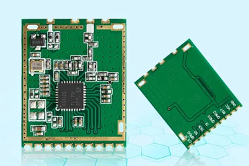
Wi-Fi and Bluetooth Coexistence Strategies
Dual-mode Wi-Fi (2.4GHz/5GHz) and Bluetooth Low Energy (BLE) are commonly integrated into smart camera PCBs to support both high-bandwidth video and low-power control commands. The PCB layout isolates the antennas for each protocol to minimize coupling, with Wi-Fi antennas placed at least 1 inch away from BLE components. For example, a printed inverted-F antenna (PIFA) for Wi-Fi might occupy a 20x10mm area on the PCB’s edge, while a chip antenna handles BLE signals in a separate corner.
Frequency hopping spread spectrum (FHSS) techniques in BLE and dynamic frequency selection (DFS) in Wi-Fi mitigate interference from neighboring devices. The firmware implements adaptive channel switching, prioritizing less congested bands based on real-time spectrum analysis. For instance, if the 2.4GHz band shows 70% channel utilization, the system automatically switches to a 5GHz channel with lower interference, even if it requires slightly higher power consumption.
Video Encoding and Compression Optimization
To reduce bandwidth requirements without sacrificing visual quality, smart cameras employ advanced video compression standards like H.264 or H.265 (HEVC). The encoder analyzes frame differences using motion estimation algorithms, generating I-frames (keyframes) at configurable intervals (e.g., every 2 seconds) and P/B-frames for intermediate data. For example, a 1080p30 stream might compress from 1.5Gbps (raw) to 2Mbps (H.265) with minimal perceptible loss, enabling smooth streaming over constrained networks.
Rate control mechanisms adjust quantization parameters (QP) dynamically based on network conditions. In low-bandwidth scenarios, the encoder increases QP values to reduce bitrate, accepting higher compression artifacts, while stable connections trigger lower QP values for improved clarity. Some designs incorporate scene complexity detection, allocating more bits to high-detail areas (e.g., foliage) and fewer bits to flat regions (e.g., skies) to optimize perceived quality.
Power Efficiency in Image Transmission Systems
Smart cameras often operate on batteries or low-voltage DC supplies, necessitating power-aware designs that extend runtime without compromising performance.
Dynamic Voltage and Frequency Scaling (DVFS)
The camera’s processor and wireless modules implement DVFS to match power consumption with workload demands. For example, during idle periods, the CPU clock speed might drop from 1GHz to 200MHz, reducing voltage from 1.2V to 0.9V and cutting power by over 80%. When motion is detected, the system ramps up to full performance within 10ms to capture and transmit high-resolution frames without delay.
Wireless transceivers use similar scaling, entering low-power listen modes when not actively transmitting. BLE advertisements, which consume microamps of current, replace continuous Wi-Fi scanning in battery-powered designs. The firmware schedules data transfers during periods of high network availability, such as when a connected router is idle, to minimize retransmission attempts and associated power costs.
Energy Harvesting and Low-Power Sleep States
To further extend battery life, some smart cameras integrate energy harvesting circuits that convert ambient light or vibrations into supplemental power. A small photovoltaic cell (e.g., 5x5mm) might generate 100μW under indoor lighting, sufficient to maintain the RTC (Real-Time Clock) and memory during extended power outages. Alternatively, piezoelectric elements can harvest energy from mechanical vibrations, such as those caused by nearby traffic or HVAC systems.
Deep sleep modes reduce power consumption to microamp levels by disabling all non-essential circuits, including the sensor and wireless modules. Wake-up triggers include hardware interrupts from motion detectors, button presses, or scheduled alarms. For example, a PIR (Passive Infrared) sensor connected to a GPIO pin can wake the camera from sleep within 50ms when motion is detected, ensuring rapid response without constant power drainage.


