Safety Requirements for PCB Assembly in Electronic Cigarettes
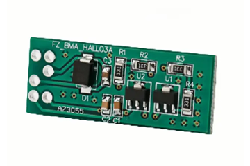
Electronic cigarettes, or vaping devices, rely on PCB assemblies to manage power delivery, control heating elements, and ensure user safety during operation. Given their direct interaction with users and exposure to liquids, heat, and electrical currents, these PCBs must adhere to stringent safety standards to prevent malfunctions such as overheating, short circuits, or battery failures. Achieving this requires careful attention to component selection, electrical isolation, thermal management, and compliance with industry regulations.
Electrical Isolation and Insulation to Prevent Short Circuits
Electronic cigarette PCBs operate in environments where condensation from e-liquids or accidental spills can create conductive paths between traces or components, leading to short circuits. To mitigate this risk, designers implement multi-layer insulation strategies, starting with conformal coatings applied to the PCB surface. These coatings, often made of acrylic, silicone, or urethane, form a protective barrier against moisture and chemicals while maintaining flexibility to accommodate thermal expansion.
Double-sided PCBs used in compact vaping devices require precise spacing between conductive layers to prevent arcing, especially near high-voltage components like battery connectors or heating coils. Clearance and creepage distances—the physical separation between traces on the same layer and across layers, respectively—are calculated based on the device’s operating voltage and environmental conditions. For example, increasing the distance between traces reduces the likelihood of electrical discharge when contaminants bridge the gap.
Isolation techniques extend to component-level design, where optocouplers or transformers electrically separate control circuits from power stages. This prevents voltage spikes or faults in the heating element circuit from propagating to sensitive areas like battery management systems (BMS). During assembly, automated optical inspection (AOI) verifies that isolation gaps meet design specifications, reducing the risk of human error during manual placement of critical components.
Thermal Management for Safe Operation of Heating Elements
The heating coil in an electronic cigarette draws significant current, generating heat that must be dissipated efficiently to avoid damaging the PCB or surrounding components. Thermal runaway, where rising temperatures accelerate component degradation, is a primary concern, as it can lead to battery explosions or device malfunctions. To manage heat, designers incorporate thermal vias—plated holes that transfer heat from the top layer of the PCB to internal or bottom layers with larger copper areas for dissipation.
High-thermal-conductivity materials, such as aluminum-core PCBs or metal-backed substrates, are sometimes used in place of traditional FR-4 to improve heat spreading. These materials reduce localized hotspots near the heating coil driver circuitry, ensuring uniform temperature distribution across the board. Temperature sensors placed close to the heating element monitor operational conditions in real time, triggering safety mechanisms like automatic shutdown if thresholds are exceeded.
During PCB layout, components sensitive to heat, such as microcontrollers or capacitors, are positioned away from the heating zone to minimize thermal stress. Additionally, solder masks with high-temperature resistance prevent degradation under prolonged exposure to heat, maintaining electrical insulation and trace integrity. Manufacturers also perform thermal cycling tests to simulate real-world usage patterns, identifying potential failure points related to repeated heating and cooling cycles.
Battery Management and Protection Against Overcharging/Discharging
Lithium-ion batteries, commonly used in electronic cigarettes, require robust protection circuits to prevent overcharging, over-discharging, and short circuits, all of which can lead to thermal events or catastrophic failure. The PCB assembly integrates a BMS that monitors battery voltage, current, and temperature, dynamically adjusting charging rates or disconnecting the battery if unsafe conditions are detected.
Key components of the BMS include overvoltage protection (OVP) circuits that halt charging when the battery reaches its maximum safe voltage and undervoltage lockout (UVLO) mechanisms that prevent discharge below a critical threshold, which can damage the battery’s internal structure. Current-limiting resistors and fuses are also embedded in the PCB to restrict excessive current flow during high-power draws or accidental shorts, safeguarding both the battery and the user.
For devices with removable batteries, PCB contacts must be designed to resist corrosion and maintain consistent electrical connectivity, even after repeated insertions. Spring-loaded or gold-plated contacts reduce resistance and minimize heat generation during charging or discharging. During assembly, automated soldering processes ensure reliable connections between the BMS and battery terminals, while X-ray inspection verifies the integrity of solder joints beneath surface-mount components.
Compliance with Regulatory Standards and Certification Requirements
Electronic cigarette PCB assemblies must comply with international safety standards to ensure market acceptance and user trust. Regulations such as the EU’s Tobacco Products Directive (TPD) and the U.S. Food and Drug Administration (FDA) guidelines impose strict limits on nicotine content, device labeling, and electrical safety. For PCBs, this translates to adherence to standards like IEC 62133 for battery safety and IPC-A-610 for electronic assembly quality.
Certification bodies such as UL or TÜV conduct independent testing to verify that PCBs meet these standards, including evaluations of flame resistance, electrical insulation, and mechanical durability. Designers incorporate safety margins into component ratings—for example, selecting capacitors with voltage ratings 20% higher than the expected operating voltage—to account for manufacturing variances or transient spikes.
Traceability is another critical aspect of regulatory compliance, as manufacturers must document every stage of the PCB assembly process, from material sourcing to final testing. This includes maintaining records of component lot numbers, solder batch identifiers, and inspection results, enabling rapid recalls or investigations if safety issues emerge post-deployment.
By prioritizing electrical isolation, thermal management, battery protection, and regulatory compliance, PCB assemblies in electronic cigarettes achieve the safety and reliability required for consumer use. These measures not only protect users from hazards like overheating or battery failures but also ensure long-term performance in a competitive market where safety is a non-negotiable feature.


